This tutorial is all about lighting up your worlds. Up to now, we've relied on default (ie none) lighting. The default headlight setting is TRUE, so up to now we've been illuminating our world with a headlight. This is all about to change. From now on, your worlds will be dazzlingly lit with an array of effects such as you have never seen before. Maybe.
The first thing to mention is the way that the VRML lighting model works. All lights have the following fields: color, ambientIntensity, and intensity. Each light has an intensity, which a value between 0 and 1 corresponding to it's brightness. It also has an ambient intensity, also between 0 and 1, which is how much light it contributes to the general ambient light in the scene. Because of this, the more lights in the scene, the brighter the ambient illumination, which makes sense. Ambient light is light that shines on every surface in the scene, simulating light scattered from other objects. Each light also has a colour associated with it, which surprisingly enough is the colour of the light it emits. The direct light emitted by a light source is calculated by intensity * color. The ambient light contributed to the scene is ambientIntensity * color. Each light source also has an area of effect, so as to keep VRML worlds enclosed and scalable. The method of doing this varies between the different types.
Most VRML browsers calculate lighting by working it out for each corner of a face, and interpolating the shading between these vertices. This means that if you have a huge face with a light source shining on the middle of it, with corners that are very distant, you will NOT get a light spot on the face. It will all be uniformly dark. This is an important thing to bear in mind. Another important point to notice is that faces are only lit if they have a Material node. Objects with textures will not be affected by lighting. This is awkward, and you may have to produce pre-lit textures to compensate if you need shading on them. Another very important thing to remember is that by default, VRML worlds will have the user's headlight ON. This will seriously screw the careful lighting in your worlds, so remember to turn it off if you feel it necessary. This is done by inserting a headlight FALSE line into a NavigationInfo node, as shown in the code sample below. We'll cover the NavigationInfo in one of the later tutorials, but for now you can just include this in your files to turn off the headlight. It just goes at the top level of the scene graph, like WorldInfo. We'll come back to it, don't worry.
NavigationInfo {
	headlight FALSE
}
More information on the VRML lighting model can be found in the specification, mirrored on this site, here, but that should be enough to get you going. I suggest that you read the lighting model spec before you do anything particularly advanced.
Right then, time to get down to business. The first light node we'll cover is the DirectionalLight node. This is a light that shines from a uniform direction, like a set of parallel rays. This gives an effect like that of the Sun, where everything is illuminated from the same direction. The DirectionalLight node does not have a location in the worlds space, but simply exists.
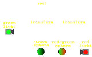
It illuminates everything that is a child of its parent, so everything at its level in the hierarchy and below. This example (code)shows the scoping of the DirectionalLight node. Both Spheres are lit by a green light from behind, but the one on the right is also lit by a red light pointing from in front of it. This is because the green light is at the top level in the file, so illuminates everything. The red light, however is grouped in the same node as the sphere it shines on. The other sphere is in a separate part of the scene graph, so is not lit. This is demonstrated in this diagram.

The DirectionalLight node has the basic light fields of intensity, color, and ambientIntensity. It also has an on field, which is simply TRUE or FALSE, indicating whether the light is on or off. It also has a direction field, which is a vector corresponding to the direction that the light shines in. The default value of 0 0 -1, for instance, indicates that the light shines from +Z towards the origin, or down the -Z axis. The full definition of the DirectionalLight node is shown below.
DirectionalLight {
	exposedField	SFFloat		ambientIntensity	0
	exposedField	SFColor		color			1 1 1
	exposedField	SFVec3f		direction		0 0 -1
	exposedField	SFFloat		intensity		1
	exposedField	SFBool		on			TRUE
}
A PointLight is light that emanates from a particular point in space, spreading equally in all directions. Unlike the DirectionalLight, this node actually has a position in space, specified in it's location field. This is the point from which the light will emanate. The effect of the PointLight is limited in a different way to the DirectionalLight. Rather than being scoped by its position in the scene hierarchy, is it scoped by its position in space. It has fields that perform this scoping, the radius field. The radius of the light is the maximum distance at which objects will be illuminated. Within this radius, the intensity of the light is affected by a set of attenuation constants. These are 3 floating point values (stored as an SFVec3f) that affect the lighting with the following formula:
1/(attenuation[0] + attenuation[1]*r + attenuation[2]*r2)
This means that the 3 values in the attenuation field are used as coefficients in a quadratic formula for the intensity of the light at a distance r. It is left up to you to experiment with different coefficients. The default value of 1 0 0 gives no attenuation, giving a sharp limit to the effect of the light. To make the light fall off linearly, you would have an attenuation of the form 0 x 0. I'll leave you to experiment, but I'll leave this node with this example (code). The set of spheres on the left is lit with attenuation constants of 0 1 0, giving a linear attenuation. The right-hand set is lit with non-linear attenuation constants of 0 0 1, causing the light to fall off in an r2 kind of way. Bear in mind that this may not look correct on your system, depending on the renderer used by your browser. Direct3D renderers do not seem to support attenuation, so don't worry if you can't see it, it's just your browser limitations. It does work, honest.
PointLight {
	exposedField	SFFloat		ambientIntensity	0
	exposedField	SFVec3f		attenuation		1 0 0
	exposedField	SFColor		color			1 1 1
	exposedField	SFFloat		intensity		1
	exposedField	SFVec3f		location		0 0 0
	exposedField	SFBool		on			TRUE
	exposedField	SFFloat		radius			100
}
The last lighting node is the SpotLight node. This, obviously enough, defines a spotlight. It has all the standard fields of the normal lighting nodes. It also has the location, radius and attenuation fields of the PointLight node. These fields have exactly the same effect as described above, giving a position, a maximum radius, and an attenuation within this radius for the light source. However, it also has a couple of other fields. The SpotLight is scoped by it's position in space in the same way as the PointLight. However, as it is a light that shines in a particular direction, as well as it's location, it also has a direction field, which defines the direction that the light points in.
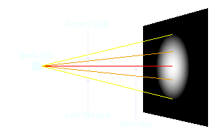
We can also specify the size of the spotlight produced with two other fields, the beamWidth and the cutOffAngle. These are angles, which define how wide the main beam will be, and how fast it fades out at the edges. Note that this cutOffAngle is completely unrelated to the attenuation. The attenuation governs how the light changes in the direction that it is shining, and cutOffAngle defines how it falls off at the edges of the beam. By default, the beamWidth is larger than the cutOffAngle, giving a sharp edge to the beam. This increases rendering performance considerably. This diagram shows how beamWidth and cutOffAngle affect the appearance of the beam.

SpotLight {
	exposedField	SFFloat		ambientIntensity	0
	exposedField	SFVec3f		attenuation		1 0 0
	exposedField	SFFloat		beamWidth		1.570796
	exposedField	SFColor		color			1 1 1
	exposedField	SFFloat		cutOffAngle		0.785398
	exposedField	SFVec3f		direction		0 0 -1
	exposedField	SFFloat		intensity		1
	exposedField	SFVec3f		location		0 0 0
	exposedField	SFBool		on			TRUE
	exposedField	SFFloat		radius			100
}
It is worth remembering that if you want any kind of special lighting effect on a surface, such as a spotlight with a soft edge, that surface will have to have many vertices on it and be made up of many faces, as VRML only does lighting at each corner. This is a very important thing to remember. If you have a light shining on the middle of a large surface, you will not get the effect you want. Also, different rendering libraries support lighting an attenuation in different ways, so lighting may appear different in different browsers. The important thing to do with lighting is to experiment, if possible with different browsers. Go to it! Next time, we'll cover advanced texturing, and then we're on to Part 3 and animation!


